Questions we are Frequently Asked
Some of the frequently asked questions we get asked are presented below:
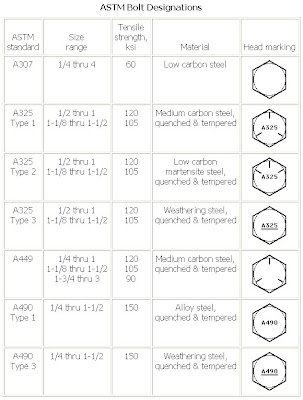
What are the marks shown on the head of a bolt?
When tightening stainless steel bolts - they tend to seize - what's happening?
I can't find the shear strength of a fastener in the specification,can you help?
What is the best way to check the torque value on a bolt?
What are the benefits of fine threaded fasteners over coarse threaded fasteners?
What methods are available for calculating the appropriate tightening torque for a bolt.
Does it matter whether you tighten the bolt head or the nut?
How do you select a fastener size for a particular application?
Does using an extension on a torque wrench change the abliity to achieve the desired torque value?
Is it okay to use a mild steel nut with a high tensile bolt?
Should I always use a washer under the bolt head and nut face?
What is the torque to yield tightening method?
How do metric strength grades correspond to the inch strength grades?
What is the difference between a bolt and a screw?
Are the use of a thin nut and a thick nut effective in preventing loosening?
Is there some standard that states how much the thread should protrude past the nut?
What are the marks shown on the head of a bolt?
head of a bolt. The manufacturer's mark is a symbol identifying
the manufacturer (or importer). This is the organisation that
accepts the responsibility that the fastener meets specified 
requirements. The grade mark is a standardised mark that identifies
the material properties that the fastener meets. For example
307A on a bolt head indicates that the fastener properties
conform to the ASTM A307 Grade A standard. The bolt head shown
at the side indicates that it is of property class 8.8 and
ML is the manufacturer's mark.
Both marks are usually located on the top of the bolt head,
most standards indicating that the marks can be raised or
depressed. Raised marks are usually preferred by manufacturers
because these can only be added during the forging process
whereas depressed marks can subsequently added (possibly with
illegitimate marks).
We have a problem when tightening stainless steel bolts - they tend to seize - whats happening?
Stainless steel can unpredictably sustain
galling (cold welding). Stainless steel self-generates an
oxide surface film for corrosion protection. During fastener
tightening, as pressure builds between the contacting and
sliding, thread surfaces, protective oxides are broken, possibly
wiped off, and interface metal high points shear or lock together.
This cumulative clogging-shearing-locking action causes increasing
adhesion. In the extreme, galling leads to seizing - the actual
freezing together of the threads. If tightening is continued,
the fastener can be twisted off or its threads ripped out.
If galling is occurring than because of high friction the
torque will not be converted into bolt preload. This may be
the cause of the problems that you are experiencing. The change
may be due to the surface roughness changing on the threads
or other similar minor change. To overcome the problem - suggestions
are:
1. Slowing down the installation RPM speed may possibly solve
or reduce the frequency of the problem. As the installation
RPM increases, the heat generated during tightening increases.
As the heat increases, so does the tendency for the occurrence
of thread galling.
2. Lubricating the internal and/or external threads frequently
can eliminate thread galling. The lubricants usually contain
substantial amounts of molybdenum disulfide (moly). Some extreme
pressure waxes can also be effective. Be careful however,
if you use the stainless steel fasteners in food related applications
some lubricants may be unacceptable. Lubricants can be applied
at the point of assembly or pre-applied as a batch process
similar to plating. Several chemical companies, such as Moly-Kote,
offer anti-galling lubricants.
3. Different combinations of nut and bolt materials can assist
in reducing or even eliminating galling. Some organisations
specify a different material, such as aluminium bronze nuts.
However this can introduce a corrosion problem since aluminium
bronze is anodic to stainless steel.
I can't find the shear strength of a fastener in the specification,
can you help?
Bolted shear joints can be designed as
friction grip or direct shear. With friction grip joints you
must ensure that the friction force developed by the bolts
is sufficient to prevent slip between the plates comprising
the joint. Friction grip joints are preferred if the load
is dynamic since it prevents fretting.
With direct shear joints the shank of the
bolts sustain the shear force directly giving rise to a shear
stress in the bolt. The shear strength of a steel fastener
is about 0.6 times the tensile strength. This ratio is largely
independent of the tensile strength. The shear plane should
go through the unthreaded shank of a bolt if not than the
root area of the thread must be used in the calculation.
What is the best way to check the torque value on a bolt?
There are three basic methods for the checking
of torques applied to bolts after their installation; namely,
taking the reading on a torque gauge when:
1. The socket begins to move away from
the tightened position in the tightening direction. This method
is frequently referred to as the "crack-on" method.
2. The socket begins to move away from
the tightened position in the un- tightening direction. This
method is frequently referred to as the "crack-off"
method.
3. The fastener is re-tightened up to a
marked position. With the "marked fastener" method
the socket approaches a marked position in the tightening
direction. Clear marks are first scribed on the socket and
onto the joint surface which will remain stationary when the
nut is rotated. (Avoid scribing on washers since these can
turn with the nut.) The nut is backed off by about 30 degrees,
followed by re-tightening so that the scribed lines coincide.
For methods 1. and 2. the breakloose torque
is normally slightly higher than the installation torque since
static friction is usually greater than dynamic friction.
In my opinion, the most accurate method is method 3 - however
what this will not address is the permanent deformation caused
by gasket creep. An alternative is to measure the bolt elongation
(if the fastener is not tapped into the gearbox). This can
be achieved by machining the head of the bolt and the end
of the bolt so that it can be accurately measured using a
micrometer. Checking the change in length will determine if
you are losing preload.
The torque in all three methods should
be applied in a slow and deliberate manner in order that dynamic
effects on the gauge reading are minimised. It must always
be ensured that the non- rotating member, usually the bolt,
is held secure when checking torques. The torque reading should
be checked as soon after the tightening operation as possible
and before any subsequent process such as painting, heating
etc. The torque readings are dependent upon the coefficients
of friction present under the nut face and in the threads.
If the fasteners are left to long, or subjected to different
environmental conditions before checking, friction and consequently
the torque values, can vary. Variation can also be caused
by embedding (plastic deformation) of the threads and nut
face/joint surface which does occur. This embedding results
in bolt tension reduction and affects the tightening torque.
The torque values can vary by as much as 20% if the bolts
are left standing for two days.
What are the benefits of fine threaded fasteners over coarse threaded fasteners?
The potential benefits of fine threads are:
1. Size for size a fine thread is stronger
than a coarse thread . This is both in tension (because of
the larger stress area) and shear (because of their larger
minor diameter).
2. Fine threads have also less tendency
to loosen since the thread incline is smaller and hence so
is the off torque.
3. Because of the smaller pitch they allow
finer adjustments in applications that need such a feature.
4. Fine threads can be more easily tapped
into hard materials and thin walled tubes.
5. Fine threads require less torque to
develop equivalent bolt preloads.
On the negative side:
1. Fine threads are more susceptible to
galling than coarse threads.
2. They need longer thread engagements
and are more prone to damage and thread fouling.
3. They are also less suitable for high
speed assembly since they are more likely to seize when being
tightened.
Normally a coarse thread is specified
unless there is an over-riding reason to specify a fine thread,
certainly for metric fasteners, fine threads are more difficult
to obtain.
What methods are available for calculating the appropriate tightening
torque for a bolt?
A high bolt preload ensures that the joint
is resistant to vibration loosening and to fatigue. In most
applications, the higher the preload - the better (assuming
that the surface pressure under the nut face is not exceeded
that is).
The preload is related to the applied torque
by friction that is present under the nut face and in the
threads. The torque value depends primarily on the values
of the underhead and thread friction values and so a single
figure cannot be quoted for a given thread size.
The stress that is often quoted is often
taken as the direct stress in the bolt as a result of the
preload. It is normally calculated as preload divided by the
stress area of the thread. Typical values vary between 50%
to 80% of the yield strength of the bolt material, in many
applications a figure of 75% of yield is used. Our TORKSense
program uses this approach and further details on this is
presented in the help file that comes with the demo program
that is available for download from our web site. (This program
also provides large databases on thread, bolting materials
and nut factors.)
It is important to note that it does not
take into account the torsional stress as a result of the
tightening torque. High friction values can push the actual
combined stress over yield if high percentages are used. (The
tensile stress from the preload coupled with a high torsional
shear stress from the torque due to thread frictional drag
results in a high combined stress.) The percentage yield approach
works well in most practical circumstances but if you are
using percentage of yield values over 75% then you could be
exceeding yield if high friction values are being used.
One way to over come this limitation is
to use the percentage of yield based upon the combined effects
of the direct stress (from the bolt preload) and the torsional
stress (from the applied torque). Using this approach to specify
torque values is more logically consistent and can reduce
the risk of the yield strength of the bolt being exceeded
- especially under high thread friction conditions. A figure
of 90% of yield is typically used here when the combined stress
(usually calculated as the Von-Mises stress) from the direct
and torsional stresses is calculated. Our Torque and BOLTCALC
programs uses this approach and a copy of the demo program
can be downloaded from our web site. The help file provided
with the demo program does provide additional information
on this topic.
Does it matter whether you tighten the bolt head or the nut?
Normally it will not matter whether the
bolt head or the nut is torqued. This assumes that the bolt
head and nut face are of the same diameter. If they are not
then it does matter.
Say the nut was flanged and the bolt head
was not. If the tightening torque was determined assuming
that the nut was to be tightened then if the bolt head was
subsequently tightened instead then the bolt could be overloaded.
Typically 50% of the torque is used to overcome friction under
the tightening surface. Hence a smaller friction radius will
result in more torque going into the thread of the bolt and
hence being over tightened.
If the reverse was true - the torque determined
assuming that the bolt head was to be tightened then if the
nut was subsequently tightened - the bolt would be under tightened.
There is also an effect due to nut dilation
that can, on occasion, be important. Nut dilation is the effect
of the external threads being pushed out due to the wedge
action of the threads. This reduces the thread stripping area
and is more prone to happen when the nut is tightened since
the tightening action facilitates the effect. Hence if thread
stripping is a potential problem, and for normal standard
nuts and bolts it is not, then tightening the bolt can be
beneficial.
How do you select a fastener size for a particular application?
When selecting a suitable fastener for
a particular application there are several factors that must
be taken into account. Principally these are:
1. How many and what size/strength do the
fasteners need to be? Other than rely upon past experience
of a similar application an analysis must be completed to
determine the size/number/strength requirements. A program
like BOLTCALC can assist you with resolving this issue.
2. The bolt material to resist the environmental
conditions prevailing. This could mean using a standard steel
fastener with surface protection or may mean using a material
more naturally corrosion resistant such as stainless steel.
The general underlying principle is to
minimise the cost of the fastener whilst meeting the specification/life
requirements of the application. Each situation must be considered
on its merit and obviously some detailed work is necessary
to arrive at a detailed recommendation.
Does using an extension on a torque wrench change the abliity to
achieve the desired torque value?
If you use an extension spanner on the
end of a torque wrench, the torque applied to the nut is greater
than that shown on the torque wrench dial.
If the torque wrench has a length L, and
the extension spanner a length E (overall length of L+E) than:
TRUE TORQUE= DIAL READING X (L+E)/L
i.e the torque will be increased.

Is it okay to use a mild steel nut with a high tensile bolt?
Nut thickness standards have been drawn
up on the basis that the bolt will always sustain tensile
fracture before the nut will strip. If the bolt breaks on
tightening, it is obvious that a replacement is required.
Thread stripping tends to be gradual in nature. If the thread
stripping mode can occur, assemblies may enter into service
which are partially failed, this may have disastrous consequences.
Hence, the potential of thread stripping of both the internal
and external threads must be avoided if a reliable design
is to be achieved. When specifying nuts and bolts it must
always be ensured that the appropriate grade of nut is matched
to the bolt grade.
The standard strength grade (or Property
Class as it is known in the standards) for many industries
is 8.8. On the head of the bolt, 8.8 should be marked together
with a mark to indicate the manufacturer. The Property Class
of the nut matched to a 8.8 bolt is a grade 8. The nut should
be marked with a 8, a manufacturer's identification symbol
shall be at the manufacturer's discretion.
Higher tensile bolts such as property class
10.9 and 12.9 have matching nuts 10 and 12 respectively. In
general, nuts of a higher property class can replace nuts
of lower property class (because as explained above, the 'weakest
link' is required to be the tensile fracture of the bolt).
Should I always use a washer under the bolt head and nut face?
Our opinion is that plain washers are best
avoided if possible and certainly, a plain washer should not
be used with a 'lock' washer. It would partly negate the effect
of the locking action and secondly could lead to other problems
(see below). Many 'lock' washers have been shown to be ineffective
in resisting loosening.
The main purpose of a washer is to distribute
the load under the bolt head and nut face. Instead of using
washers however the trend as been to the use of flanged fasteners.
If you compute the bearing stress under the nut face it often
exceeds the bearing strength of the joint material and can
lead to creep and bolt preload loss. Traditionally a plain
washer (that should be hardened) is used in this application.
However they can move during the tightening process (see below)
causing problems.
Research indicates that the reason why
fasteners come loose is usually caused by transverse loadings
causing slippage of the joint. The fastener self loosens by
this method. When using impact tightening tools there is a
large variability in the preload achieved by the fastener.
The tightening factor is between 2.5 and 4 for this method.
(The tightening factor is the ratio of max preload to min.
preload.) Software such as our BOLTCALC program allow for
this by basing the design on the lowest anticipated preload
that will be achieved in the assembly. Because of changes
in the thread condition itself - different operators etc.
it could be that lower values of preload are being achieved
even though the assemblies may appear to be identical.
One problem that can occur with washers
is that they can move when being tightened so that the washer
can rotate with the nut or bolt head rather than remaining
fixed. This can affect the torque tension relationship.
What is the torque to yield tightening method?
Torque to yield is the method of tightening
a fastener so that a high preload is achieved by tightening
up the yield point of the fastener material. To do this consistently
requires special equipment that monitors the tightening process.
Basically, as the tightening is being completed the equipment
monitors the torque verses angle of rotation of the fastener.
When it deviates from a specified gradient by a certain amount
the tool stops the tightening process. The deviation from
a specified gradient indicates that the fastener material
as yielded.
The torque to yield method is sometimes
called yield controlled tightening or joint controlled tightening.
How do metric strength grades correspond to the inch strength grades?
Some details on conversion guidance between
metric and inch based strength grades is given in section
3.4 of the standard SAE J1199 (Mechanical and Material Requirements
for Metric Externally Threaded Steel Fasteners).
Metric fastener strength is denoted by
a property class which is equivalent to a strength grade.
Briefly:
Class 4.6 is approximately equivalent to
SAE J429 Grade 1 and ASTM A307 Grade A
Class 5.8 is approximately equivalent to
SAE J429 Grade 2
Class 8.8 is approximately equivalent to
SAE J429 Grade 5 and ASTM A449
Class 9.8 is approximately 9% stronger
than equivalent to SAE J429 Grade 5 and ASTM A449
Class 10.9 is approximately equivalent
to SAE J429 Grade 8 and ASTM A354 Grade BD
For information there is no direct inch
equivalent to the metric 12.9 property class.
What is the difference between a bolt and a screw?
Historically the difference between a bolt
and a screw was that the screw was threaded to the head whereas
the bolt had a plain shank. However I would say that now this
could cause you a problem if you made this assumption when
specifying a fastener. The definition used by the Industrial
Fastener Institute (IFI) is that screws are used with tapped
holes and bolts are used with nuts.
Obviously a standard 'bolt' can be used
in a tapped hole or with a nut. The IFI maintain that since
this type of fastener is normally used with a nut then it
is a bolt. Certain short length bolts are threaded to the
head - they are still bolts if the main usage is with nuts.
Screws are fastener products such as wood screws, lag screws
and the various types of tapping screws. The IFI terminology
and definition has been adopted by ASME and ANSI.
Are the use of a thin nut and a thick nut effective in preventing loosening?
I had been of the opinion that when two
nuts were being used to lock a thread, the thicker of the
two nuts should go next to the joint. I had this as one of
the 'tips for the day' on some software and a couple of years
ago was taken to task that this was wrong. The thin nut he
said should go next to the joint.
My reasoning was that nut heights had been
decided by establishing the least height that would ensure
that the bolt would break before the threads started to shear.
So if you wanted to get the maximum preload into the fastener
then the thick nut should go first so that thread stripping
was prevented. If you put the thin nut first, the preload
would be limited by the thread stripping (whose failure may
not be obvious at the time of the nuts were tightened). Putting
the thin nut on top of the thick nut, I thought, would assist
in preventing the thick nut self-loosening. I had also seen
that
using two nuts was a popular method on old machinery - and
the ones that I had seen all had the thin nut on top of the
thick nut.
The correct procedure, I was told, was
to put the thin nut on first, tighten it to 30% or so of the
full torque and then tighten the thick nut on top of it to
the full torque value. You have to take care that the thin
nut does not rotate when you are tightening the thick nut.
The tightening of the thick nut would impose a preload on
the joint equivalent to that which would be obtained from
100 - 30 = 70% of the tightening torque (approximately anyway).
The idea is that the bolt threads engaging on the thin nut
disengage so that the thick nut takes the preload by taking
up the backlash on the threads of the thin nut. The thin nut
being jammed (hence the alternative name - jam nut) against
the thick
nut. This helps to prevent self-loosening and improves the
fastener's fatigue performance by modifying the load distribution
within the threads. Doing it the other way, thin nut on top
of the thick nut, does not jam the parts together sufficiently.
Two years on and I am still unconvinced.
I am still asked the two nut question but I always tend to
recommend other more modern ways of locking the threads. I
think that the reasons that I am not easy with the method
is that it is too reliant upon the skill of the person tightening
the joint. There is also the amount of backlash in the threads
(you could strip the threads of the small nut if it was a
tight fit) and the preload will be down on what it could be
as well.
Is there some standard that states how much the thread should protrude past the nut?
There are some building codes that stipulates that there must
be at least one thread protruding through the nut. However
it is common practice to specify that at least one thread 
pitch must protrude across a range of industries. Typically
the first few pitches of the thread can be only partially
formed because of a chamfer etc.
Nut thickness standards have been drawn
up on the basis that the bolt will always sustain tensile
fracture before the nut will strip. If the bolt breaks on
tightening, it is obvious that a replacement is required.
Thread stripping tends to be gradual in nature. If the thread
stripping mode can occur, assemblies may enter into service
which are partially failed, this may have disastrous consequences.
Hence, the potential of thread stripping of both the internal
and external threads must be avoided if a reliable design
is to be achieved. When specifying nuts and bolts it must
always be ensured that the appropriate grade of nut is matched
to the bolt grade.
In cases of when a threaded fastener is
tapped into a plate or a block it is usually the case that
the fastener and block materials will be of different strengths.
If the criteria is adopted that the bolt must sustain tensile
fracture before the female thread strips, the length of thread
engagement required can be excessive and can become unrealistic
for low strength plate/block materials. Tolerances and pitch
errors between the threads can make the engagement of long
threads problematical.
In summary the full height of the nut is
to be used if you are to avoid thread stripping. Have a look
at information on the website on the BOLTCALC program and
thread stripping - there is a tutorial/presentation available
from the website.
In terms of maximum protrusion I have not
come across any guidelines on this point other then minimise
to avoid wasting material.
See shortbolting.htm
for more information on this topic.


